Allow the amp to warm up for at least 30 minutes while watching it carefully. IF ANY OF THE OUTPUT TUBES BEGIN TO GLOW CHERRY RED IMMEDIATELY DISCONNECT THE AC LINE CORD AND INSPECT THE AMPLIFIER FOR TROUBLE. The output tubes should show no red color during their normal operation or during testing.
DC BALANCE: The DC balance adjustment must be done without an input signal feeding into the amp. It is best to short the inputs to ensure no stray signal pick up.
Hold the meter selector switch in channel A position. With no signal applied, adjust channel A DC balance control until the meter reads exactly at the center.
Repeat for channel B DC balance.
AC BALANCE: Connect a 16 ohm, 20 watt resistor between terminals marked "G" and "16" on the channel A speaker terminal strip. Note: you can use an 8 ohm 20 watt resistor, just hook it to the 8 ohm terminal instead of the 16 ohm. Using a standard shielded phono patch cord, connect the 60 cycle test signal from the Test Signal jack to the channel A input jack. To avoid overheating the resistor, prolonged testing should be avoided.
Hold the meter selector switch in channel A position and adjust channel A AC Balance control until meter reads exactly at the center.
Remove the phono patch cord from channel A input and connect to channel B input. Move the resistor to terminals "G" and "16" (or 8, if using an 8 ohm resistor) on the channel B speaker terminal strip. (NOTE: The resistor will be quite hot.)
Repeat the channel A procedure to set the channel B AC balance.
Tip: The meter pointer may not rest exactly at the mid-scale balance mark with the meter off. For optimum results note where the needle sits at rest, and adjust both the DC bias and the AC balance to that needle position.
Don't forget, adjust DC balance first! Be sure the meter switch is turned off when finished.
| Pin# | ||||||||
Voltage specs are DC, except as noted. All measurements are referenced to ground. Variations of 10-20% in the readings can usually be considered normal, and some are very tube dependent.
* These voltages can and should vary with the DC balance pot settings. They will not
normally be equal.
# These voltages may differ due to differences in each tube's bias current. They should be very close
to equal with DC balance properly set, and no signal applied to the amplifier.
@@ These pins may be used as tie points (depending on construction), so there may be voltage present.
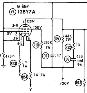
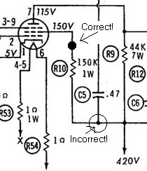
The screen bypass cap connection to both input stage tubes is drawn incorrectly. If you wire it up as shown, the screen
bypass cap (C5, .47 uf) is out of the screen circuit, and the result is no bass response at all. Make the correction and all
is good! The screen connection is shown wrong, with C5 connected directly from the 420 volt source to the 470
ohm cathode resistor. This capacitor should go between the 150K screen
resistor and the tube pin, pin 8 (the pin number isn't shown).
To Home Page To Tubes Page To H-K Citation Kits and Parts Page To Citation II adjustment page
To Citation Modifications Page To Citation Resources Page (under construction)